


a) if we get same value on both end of crystal then u need to change crystal with same value.
b) if we get difference value then your crystal is ok.
Crystal Info:
14.3=Power generator IC
32.67MHz=RTC (Real Time Clock) Crystal à to save Data/Time in BIOS.
25.0 = Lan Crystal
Lan IC Manufacturer:
Intel
Realtek
Athros
Dlink
Digilink
Devicom
DIGICOM
SOund IC Manufacturer
Yamaha
Realtek
Context
Switch Mode power supply
(a) AT - ADVANCED TECHNOLOGY
PIN- 12
(B) ATX 1.0 - Advanced Technology Extended
20 pin connector
20+4 pin (4 pin = auxiliary connector specially design for CPU power supply.)
ATX 2.0 - 24 PIN CONNECTOR
How to check SMPS?
Shot Green -- Black then smps fan need to rotate means your smps is 80% is ok.
for other 20% check your smps hardware load.
orange +3.3v
red +5v
yellow +12v
gray 5v
blue -10/12 v
violet 5v
black - gnd
green - power good signal
SMPS Manufacturer?
1) Enhanced
2) VIP
3) Powerman
4) i-ball
5) Coller-master
RAM Error Code?
(A) INTEL
if Old M/B then it gives continous beep means RAM problem, remove & refit RAM again or
also clean the golden track of RAM.
if 3 beep found then also RAM issue in Intel M/B. Follow same step mention above/
(B) ASUS M/B
1 long 2 shot bee means ram issue.
If 1 beep then your system is ok.
Rajani Electronics- near navsari bazar
easy electronics - 98257 03800
mayur ele. - 0261 - 2417698/2601398 delhi Gate
How to verify that your problem with Motherboard or RAM?
Ans: 1st check SMPS voltage as per standard colors.
If we get it ok then remove all connections from M/B of HDD,DVD-RW, etc
Also remove RAM from M/B then power on your system.
If Intel M/B then:
a) For Old Intel M/B:it gives constant beep.
b) For new Intel M/B:it gives 3 beeps.
If ASUS M/B then:
it gives 1 long 2 shot beep.
Here if we get beep then your M/B is ok & problem with your RAM. Replace/Clean the RAM & refitted again to solve
the problem.
If we doesn't get any beep means problem with your M/B. Check all components on M/B.
But if we get single (1) beep means your system is ok. (working fine)
RAM Manufacturer?
1) Hyundai Hynix
2) Samsung
3) Samtronics
4) Dynet
5) Transcedent
6) I-ball
7) Cheetha
8) Kingstone
9)
How to check RAM? (For Desktop Reference)
|
No |
RAM Type |
Notch |
Pin Configuration |
Vdc |
|
1 |
EDO (Extended Data Out) |
1 |
72/144 |
5 vdc |
|
2 |
SD-RAM (Synchronous Dynamic RAM) |
2 |
168 |
3.3Vdc |
|
3 |
DDR 1 (Dual Data Rate/Double Data Rate) |
1 |
184 |
2.5Vdc |
|
4 |
DDR2 |
1 |
240 |
1.8Vdc |
|
5 |
DDR3 |
1 |
240 |
1.5Vdc |
|
6 |
DDR4 |
1 |
240 |
1.2 Vdc |
(For Laptop only)
|
No |
RAM Type |
Notch |
Pin Configuration |
Vdc |
|
1 |
SD-RAM (Synchronous Dynamic RAM) |
1 |
144 |
3.3Vdc |
|
2 |
DDR 1 (Dual Data Rate/Double Data Rate) |
1 |
200 |
2.5Vdc |
|
3 |
DDR2 |
1 |
200 |
1.8Vdc |
|
4 |
DDR3 |
1 |
204 |
1.5Vdc |
============================== ====================
Floppy Disk Drive Storage Size:
720KB (5 1/4")
1.44MB(HD=High Density Storage) size =3.5 inch
2.88MB(UHD=Ultra HD) =3.5 inch
FDD Power Connector : Burg / Mini Molex Connector
FDD data pin configuration : 34-pin
-----------------------------------------------------------------------------------------------
SMPS power supply connector use = Mini-Molex/Burg connector
FDD = Floppy Disk Drive
Floppy Disk size = 3.5"
RED = +5Vdc
Yellow = +12Vdc
HDD (Hard Disk Drive)
ATA = Advanced Technology Attachment
IDE = Integrated Drive Electronics
PATA = Parallel Advanced Technology Attachment (40-Pin Connector for Data/4 pin Molex Connector for power connection)
SATA = Serial Advanced Technology Attachment ( 7 pin Data Connection and 15 Pin Power Connection)
Molex connector = HDD/DVD device connect. (4 pin power connection)
MiniMolex = used for FDD ( Floppy Disk Drive) its 4 pin power connction
IDE/ATA/PATA--->HDD,CD/DVD drive attached
SSD = Solid State Drive
Laptop HDD size = 2.5 Inch
Desktop HDD Size = 3.5 Inch
LASER = Light Amplification Simulated Emission for Radiation
CD = Compact Disk = 700MB
DVD = Digital Versatile Disk = 4.7GB
Blue Ray Disk = 20GB up to 100GB
Processor Types:
1) Pin processor (PGA = Pin Grid Array)
2) Pinless Processor (LGA = Land Grid Array)
Processor Manufacturer company
1) Intel
2) AMD (Advanced Micro Device)
LGA775 = Core2 Duo/Quad Core processor
LGA1156 = Intel i3/i5
LGA1366 = Intel i7
Processor Type:
1) RISC = Reduced Instruction Set Computing (Mainly used for Desktop and Laptop purpose) --Less Cost
2) CISC = Complex Instruction Set Computing (Mainly used for Workstation/Server purpose)--Costly processor
SMPS Types:
1) AT = Advanced Technology (12-pin connector)
2) ATX = Advanced Technology Extended (20-pin connector)
It has Auxiliary Port for Processor Power supply only. (4-pin connector)
ATX versions:
1) ATX V.1 = 20 Pin connector
2) ATX V.2 = 24 Pin Connector
Why we use Battery or CMOS Cell?
To save your BIOS settings we use CMOS cell.
DIP Switch = Dual In-line Pin Switch
Motherboard Form Factor Types:
AT (Advanced Technology)
ATX (Advanced Technology Extended)
BTX (Balance Technology Extended)
Mini-ATX
NLX (New Low Profile Extended)
I/O Ports
USB = Universal Serial Bus (4-pin connector, use with any device attachment)
USB operate on +5Vdc.
USB Types/Version?
USB1.1 = 12Mbps
USB2.0 = 480Mbps
USB3.0 = 5Gbps
- USB is hot swappable device and we can maximum connector 127 devices at the same port.
IEEE1394/Firewire:
(IEEE = Institute Of Electrical and Electronic Engineer) 1394
Firewire is 6 pin connector.
Speed = 400Mbps and we can connect maximum 63 devices only.
CPU cases types:
1) Tower based cpu case
2) Rack based cpu case
DRAM Types:
FPM = Fast Page Mode
EDO = Extended Data Out
SDRAM = Synchronous Dynamic RAM
DDR1/2/3 = Dual Data Rate 1/2/3
RAM Type as Module wise?
1) SIMM = Single Inline Memory Module
2) DIMM = Dual Inline Memory Module
3) RIMM = Rambus Inline Memory Module
4) XIMM = Extended Inline Memory Module
(RAM Configuration for Desktop Motherboard Only)
|
No |
RAM Type |
Notch |
Pin Number |
V(dc) |
|
1 |
FPM (Fast Page Mode) – Obsolete |
1 |
72 |
5 |
|
2 |
EDO (Extended Data Out) – Obsolete |
1 |
72/144 |
5 |
|
3 |
SD-RAM (Synchronous Dynamic RAM) – Obsolete |
2 |
168 |
3.3 |
|
4 |
DDR1 (Dual Data Rate) |
1 |
184 |
2.5 |
|
5 |
DDR2 |
1 |
240 |
1.8 |
|
6 |
DDR3 |
1 |
240 |
1.5 |
(RAM Configuration for Laptop) SoDIMM (Small Outline Dual Inline Memory Module)
|
No |
RAM Type |
Notch |
Pin Number |
V(dc) |
|
1 |
SD-RAM (Synchronous Dynamic RAM) – Obsolete |
1 |
144 |
3.3 |
|
2 |
DDR1 |
1 |
200 |
2.5 |
|
3 |
DDR2 |
1 |
204 |
1.8 |
|
4 |
DDR3 |
1 |
204 |
1.5 |
Computer POST and beep codes
The computer POST (power-on self-test) checks a computer's internal hardware for compatibility and connection before starting the remainder of the boot process. If the computer passes the POST, the computer may give a single beep (some computers may beep twice) as it starts and continue to boot. However, if the computer fails the POST, the computer will either not beep or generate a beep code that tells the user the source of the problem.
If your computer has an irregular POST or a beep code not mentioned below, follow the POST troubleshooting steps to determine the failing hardware component.
AMI BIOS beep codes
Award BIOS beep codes
Dell beep codes
IBM BIOS beep codes
Macintosh startup tones
Phoenix BIOS beep codes
Motherboard help
AMI BIOS beep codes
Below are the AMI BIOS Beep codes that can occur. However, because of the wide variety of different computer manufacturers with this BIOS, the beep codes may vary.
|
Beep Code |
Descriptions |
|
1 short |
DRAM refresh failure |
|
2 short |
Parity circuit failure |
|
3 short |
Base 64K RAM failure |
|
4 short |
System timer failure |
|
5 short |
Process failure |
|
6 short |
Keyboard controller Gate A20 error |
|
7 short |
Virtual mode exception error |
|
8 short |
Display memory Read/Write test failure |
|
9 short |
ROM BIOS checksum failure |
|
10 short |
CMOS shutdown Read/Write error |
|
11 short |
Cache Memory error |
|
1 long, 3 short |
Conventional/Extended memory failure |
|
1 long, 8 short |
Display/Retrace test failed |
|
two-tone siren |
Low CPU Fan speed, Voltage Level issue |
Below are Award BIOS Beep codes that can occur. However, because of the wide variety of different computer manufacturers with this BIOS, the beep codes may vary.
|
Beep Code |
Description |
|
1 long, 2 short |
Indicates a video error has occurred and the BIOS cannot initialize the video screen to display any additional information |
|
1 long, 3 short |
Video card not detected (reseat video card) or bad video card |
|
Beeps repeating endlessly |
RAM problem. |
|
Repeated high frequency beeps while PC is running |
Overheating processor (CPU) |
|
Repeated beeps alternating high & low frequency |
Issue with the processor (CPU), possibly damaged |
If any other correctable hardware issues are found, the BIOS displays a message.
|
Beep Code |
Description |
|
1 beep |
BIOS ROM corruption or failure |
|
2 beeps |
Memory (RAM) not detected |
|
3 beeps |
Motherboard failure |
|
4 beeps |
Memory (RAM) failure |
|
5 beeps |
CMOS Battery failure |
|
6 beeps |
Video card failure |
|
7 beeps |
Bad processor (CPU) |
For other Dell beep codes, please refer to Dell's Beep Codes and PSA Diagnostics Chart page.
Below are general IBM BIOS Beep codes that can occur. However, because of the wide variety of models shipping with this BIOS, the beep codes may vary.
|
Beep Code |
Description |
|
No Beeps |
No Power, Loose Card, or Short. |
|
1 Short Beep |
Normal POST, computer is ok. |
|
2 Short Beep |
POST error, review screen for error code. |
|
Continuous Beep |
No Power, Loose Card, or Short. |
|
Repeating Short Beep |
No Power, Loose Card, or Short. |
|
1 Long and 1 Short Beep |
Motherboard issue. |
|
1 Long and 2 Short Beeps |
Video (Mono/CGA Display Circuitry) issue. |
|
1 Long and 3 Short Beeps. |
Video (EGA) Display Circuitry. |
|
3 Long Beeps |
Keyboard or Keyboard card error. |
|
1 Beep, Blank or Incorrect Display |
Video Display Circuitry. |
|
Tones |
Error |
|
Error Tone. (two sets of different tones) |
Problem with logic board or SCSI bus. |
|
Startup tone, drive spins, no video |
Problem with video controller. |
|
Powers on, no tone. |
Logic board problem. |
|
High Tone, four higher tones. |
Problem with SIMM. |
Below are the beep codes for Phoenix BIOS Q3.07 OR 4.X
|
Beep Code |
Description and what to check |
|
1-1-1-1 |
Unconfirmed beep code. Reseat RAM chips or replace RAM chips as possible solution |
|
1-1-1-3 |
Verify Real Mode. |
|
1-1-2-1 |
Get CPU Type. |
|
1-1-2-3 |
Initialize system hardware. |
|
1-1-3-1 |
Initialize chipset registers with initial POST values. |
|
1-1-3-2 |
Set in POST flag. |
|
1-1-3-3 |
Initialize CPU registers. |
|
1-1-4-1 |
Initialize cache to initial POST values. |
|
1-1-4-3 |
Initialize I/O. |
|
1-2-1-1 |
Initialize Power Management. |
|
1-2-1-2 |
Load alternate registers with initial POST values. |
|
1-2-1-3 |
Jump to UserPatch0. |
|
1-2-2-1 |
Initialize keyboard controller. |
|
1-2-2-3 |
BIOS ROM checksum. |
|
1-2-3-1 |
8254 timer initialization. |
|
1-2-3-3 |
8237 DMA controller initialization. |
|
1-2-4-1 |
Reset Programmable Interrupt Controller. |
|
1-3-1-1 |
Test DRAM refresh. |
|
1-3-1-3 |
Test 8742 Keyboard Controller. |
|
1-3-2-1 |
Set ES segment to register to 4 GB. |
|
1-3-3-1 |
28 Autosize DRAM. |
|
1-3-3-3 |
Clear 512K base RAM. |
|
1-3-4-1 |
Test 512 base address lines. |
|
1-3-4-3 |
Test 512K base memory. |
|
1-4-1-3 |
Test CPU bus-clock frequency. |
|
1-4-2-4 |
Reinitialize the chipset. |
|
1-4-3-1 |
Shadow system BIOS ROM. |
|
1-4-3-2 |
Reinitialize the cache. |
|
1-4-3-3 |
Autosize cache. |
|
1-4-4-1 |
Configure advanced chipset registers. |
|
1-4-4-2 |
Load alternate registers with CMOS values. |
|
2-1-1-1 |
Set Initial CPU speed. |
|
2-1-1-3 |
Initialize interrupt vectors. |
|
2-1-2-1 |
Initialize BIOS interrupts. |
|
2-1-2-3 |
Check ROM copyright notice. |
|
2-1-2-4 |
Initialize manager for PCI Options ROMs. |
|
2-1-3-1 |
Check video configuration against CMOS. |
|
2-1-3-2 |
Initialize PCI bus and devices. |
|
2-1-3-3 |
Initialize all video adapters in system. |
|
2-1-4-1 |
Shadow video BIOS ROM. |
|
2-1-4-3 |
Display copyright notice. |
|
2-2-1-1 |
Display CPU Type and speed. |
|
2-2-1-3 |
Test keyboard. |
|
2-2-2-1 |
Set key click if enabled. |
|
2-2-2-3 |
56 Enable keyboard. |
|
2-2-3-1 |
Test for unexpected interrupts. |
|
2-2-3-3 |
Display prompt Press F2 to enter SETUP. |
|
2-2-4-1 |
Test RAM between 512 and 640k. |
|
2-3-1-1 |
Test expanded memory. |
|
2-3-1-3 |
Test extended memory address lines. |
|
2-3-2-1 |
Jump to UserPatch1. |
|
2-3-2-3 |
Configure advanced cache registers. |
|
2-3-3-1 |
Enable external and CPU caches. |
|
2-3-3-3 |
Display external cache size. |
|
2-3-4-1 |
Display shadow message. |
|
2-3-4-3 |
Display non-disposable segments. |
|
2-4-1-1 |
Display error messages. |
|
2-4-1-3 |
Check for configuration errors. |
|
2-4-2-1 |
Test real-time clock. |
|
2-4-2-3 |
Check for keyboard errors |
|
2-4-4-1 |
Set up hardware interrupts vectors. |
|
2-4-4-3 |
Test coprocessor if present. |
|
3-1-1-1 |
Disable onboard I/O ports. |
|
3-1-1-3 |
Detect and install external RS232 ports. |
|
3-1-2-1 |
Detect and install external parallel ports. |
|
3-1-2-3 |
Re-initialize onboard I/O ports. |
|
3-1-3-1 |
Initialize BIOS Data Area. |
|
3-1-3-3 |
Initialize Extended BIOS Data Area. |
|
3-1-4-1 |
Initialize floppy controller. |
|
3-2-1-1 |
Initialize hard disk controller. |
|
3-2-1-2 |
Initialize local bus hard disk controller. |
|
3-2-1-3 |
Jump to UserPatch2. |
|
3-2-2-1 |
Disable A20 address line. |
|
3-2-2-3 |
Clear huge ES segment register. |
|
3-2-3-1 |
Search for option ROMs. |
|
3-2-3-3 |
Shadow option ROMs. |
|
3-2-4-1 |
Set up Power Management. |
|
3-2-4-3 |
Enable hardware interrupts. |
|
3-3-1-1 |
Set time of day. |
|
3-3-1-3 |
Check key lock. |
|
3-3-3-1 |
Erase F2 prompt. |
|
3-3-3-3 |
Scan for F2 key stroke. |
|
3-3-4-1 |
Enter SETUP. |
|
3-3-4-3 |
Clear in POST flag. |
|
3-4-1-1 |
Check for errors |
|
3-4-1-3 |
POST done - prepare to boot operating system. |
|
3-4-2-1 |
One beep. |
|
3-4-2-3 |
Check password (optional). |
|
3-4-3-1 |
Clear global descriptor table. |
|
3-4-4-1 |
Clear parity checkers. |
|
3-4-4-3 |
Clear screen (optional). |
|
3-4-4-4 |
Check virus and backup reminders. |
|
4-1-1-1 |
Try to boot with INT 19. |
|
4-2-1-1 |
Interrupt handler error. |
|
4-2-1-3 |
Unknown interrupt error. |
|
4-2-2-1 |
Pending interrupt error. |
|
4-2-2-3 |
Initialize option ROM error. |
|
4-2-3-1 |
Shutdown error. |
|
4-2-3-3 |
Extended Block Move. |
|
4-2-4-1 |
Shutdown 10 error. |
|
4-3-1-3 |
Initialize the chipset. |
|
4-3-1-4 |
Initialize refresh counter. |
|
4-3-2-1 |
Check for Forced Flash. |
|
4-3-2-2 |
Check HW status of ROM. |
|
4-3-2-3 |
BIOS ROM is OK. |
|
4-3-2-4 |
Do a complete RAM test. |
|
4-3-3-1 |
Do OEM initialization. |
|
4-3-3-2 |
Initialize interrupt controller. |
|
4-3-3-3 |
Read in bootstrap code. |
|
4-3-3-4 |
Initialize all vectors. |
|
4-3-4-1 |
Boot the Flash program. |
|
4-3-4-2 |
Initialize the boot device. |
|
4-3-4-3 |
Boot code was read OK. |
|
two-tone siren |
Low CPU Fan speed, Voltage Level issue |
Types of Buses:
1) Address Bus
2) Memory Bus
3) System Bus
4) Control Bus
5) Data Bus
Motherboard Bus speed:
8X, 16X, 32X, 64X, and 128X
PCI (Peripherals Components Interconnect)
PCI-X = PCI-Express which gives high speed support for hardware components.
What is the current Bus speed into Motherboard?
64-bit
------Out dated technology-------------------
ISA(Industry Standard Architecture) 8 to 16-bit speed
EISA = Enhanced ISA
MCA = Micro Channel Architecture
VESA=Video Electronic Standard Architecture
--------------------------Current technologies-------
AGP = Accelerated Graphics Port - used for display purpose.
PCI Slot/Expansion Slot/Peripheral Slot/Controller Slot = 32-64 bit speed
PCI-X = 128-bit speed
PCMCIA (Personal Computer Memory Card International Associate)
Use as a expansion purpose in laptop.
Serial Port:
----------
9-Pin Male connector
Use for Modem and SCADA system monitoring purpose (Industrial use)
Serial Port color : Green
Serial port is also known as a RS-232 (Recommended Standard - 232 means it pin-2 is working as a
input then pin-3 becomes output and if pin2 working as a output then pin3 becomes as a input)
Speed : 1bit/sec
Parallel Port:
25-Pin Female Connector
Color: Magenta
Use : Printing and old scanner connection purpose.
Speed : 8bit/sec
-----------------------------------------RAID----------
Redundancy Array of Inexpensive Disk
RAID is used for backup HDD purpose means we have to install more then 1 HDD in system.
Data will store into both or more HDD and if any one HDD goes fail then our other HDD will give data.
means our data is retrievable format. no data loss.
RAID Types:
1) Simple Volume (1 HDD)
2) Spanned Volume (minimum 1 and maximum up to 32 HDD)
3) Stripped Volume (2 HDD)-RAID 0
4) Stripped with Partiy Volume (3 HDD) RAID-5
5) Mirror Volume (2 HDD)-RAID 1
(Debug Card)use for motherboard troubleshooting.
-----------Power Supply----------------
Power Supply Types:
1) SMPS = Switch Mode Power Supply
2) UPS = Uninterruptable Power Supply
Types of UPS:
(1) Online UPS
(2) Offline UPS
(3) Line Interactive UPS (Current version)
Why we use UPS?
Ans: UPS is use when our main power supply fail then it automatically switch power source from battery.
UPS also gives constant AC Power supply in output.
Components inside UPS?
(1) Logic board
(2) Transformer
(3) Battery
------------------------------------------------------------------------------------------------------------------------------------------
Display Adapters:
1) VGA = Video Graphics Adapter (Analog Type) (15 – Pin connector with Blue color)
2) DVI = Digital Video Interface (Analog and Digital both support) (24 pin with White color connector)
3) HDMI = High Definition Multimedia Interface (Digital support) (19-up to 29 pin connector)
4) S-Video = Standard Video (4pin connector with Black color connector)
Monitor Types :
1) CRT = Cathode Ray Tube
2) LCD = Liquid Crystal Display
3) TFT = Thin Film Transistor
4) LED = Light Emitting Diode
Types of Printers?
1) Impact Printers (DMP=Dot Matrix Printers, LMP=Line Matrix Printers, Passbook Printers) EPSON, Wipro, TVSE
2) Non Impact Printers
(i) Inkjet Printers
Types of Inkjet Printers (a) Piezo Technology - CANON (b) Thermal Technology – HP, Lexmark, and Brother etc…
(ii) LaserJet Printers – HP, Lexmark, CANON, Brother, Xerox, etc…..
Printers Connection Interfaces:
1) Serial Cable – Out-dated – 9 – pin connector
2) Parallel Cable – 25 Pin connector (36 – Pin Centronics Connector – Printer Side)
3) USB Cable – 4 Pin Connector
4) Firewire Cable – Not in use
5) Wireless Cable
6) SCSI Connector
DMP = Dot Matrix Printers
DMP printer Types: (Paper Size Wise)
a) 80 – Column Printer
b) 132 – Column Printer
DMP Printer Types : (Head wise)
1) 9 – Pin
2) 24 – Pin
Dot Matrix Printer Parts List
1) Print Head (9/24-pin model)
2) Head Cable
3) Carriage Motor
4) Carriage Assembly
5) Carriage Rod
6) Carriage Belt
7) Paper Feed Motor
8) Paper Feed Gear Set
9) Ribbon Drive Assembly
10) Pully
11) Knob
12) Platen Unit
13) SMPS & Logic Board
14) Front Panel with switch
15) PTU (Paper Tension Unit)
16) Tractor Unit/assembly
17) Left & Right Sprocket
18) Left & Right Tractor Frame
19) Ribbon Mask & Ribbon Mask Holder
20) Lever – 2
21) Sensor (HP,PE,FT,PG sensors)
22) Paper Pickup roller
Q) Types of Printer as per paper-wise?
A) (1) 80-Column (2) 132-Column
Q) Types of Dot Matrix Print Head?
A) (1) 9- Pin Print head (whatever model start with LX/EX which having 9-pin)
(2) 24-Pin Print Head (whatever model start with LQ/HQ which having 24-pin)
Q) Types of Motor?
A) (1) Spindle Motor (2) Steeper Motor
Q) Advantage of Dot Matrix Printers?
1) We can print multiple paper at the same time.
2) Less print cost per paper.
3) Less maintenance.
Q) Disadvantage of Dot Matrix Printers?
1) Noisy Printers
2) Low Print Quality.
3) Only one color print support.
4) Time consummation during print.
Inkjet Printer Parts
1) Print Cartridge (Black, Color)
2) Carriage Block
3) Head Cable
4) Station Block/Assembly
5) Cleaning Unit/Purged Unit
6) Paper Pickup Roller
7) Paper feed gear set
8) Sensors
9) Carriage Belt
10) Carriage Rod
11) Cleaning Pad
12) SMPS + Logic Card
13) Paper feed motor
14) Carriage motor
15) Encoder Strip/Stabilizer Bar
Colors:
C=Cyan
M=Magenta
Y=Yellow
K=Black
Types of inkjet printers:
1) Thermal Technology
HP/CANON/BROTHER/LEXMARK
2) Piezo-Electric Technology
Epson
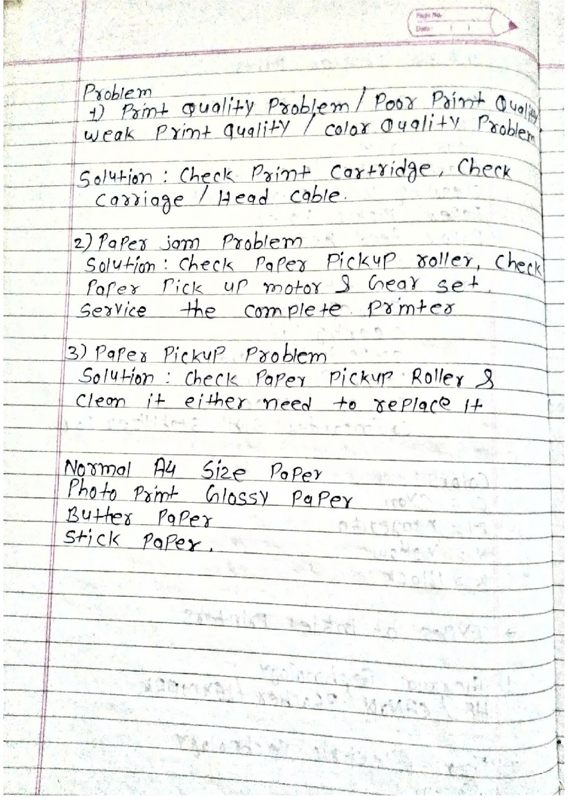
Problem:
1) Print Quality Problem/Poor Print Quality/Weak Print Quality/Color Quality problem
Solution: Check Print Cartridge, Check Carriage/Head Cable,
2) Paper Jam Problem
Solution: Check Paper Pickup roller, Check Paper pick up motor & Gear Set, Service the complete printer.
3) Paper Pickup problem
Solution: Check Paper Pickup Roller & clean it either need to replace it.
Normal A4 size paper
Photo Print: Glossy paper
Butter Paper
Stick paper
Types of Scanner:
1) Flat-bed scanner – Less Cost, Less Speed and need to change paper on every scan image.
2) Sheet Fed Scanner – Fast speed with high cost.
3) Drum Scanner – Out date
4) Hand Held Scanner – Use LED technology with Thermal paper use in Malls.
Scanner Manufacturer:
HP/Canon/Epson/Lexmark/UMAX/Brother/Kodak/Xerox etc
Scanner Parts List:
Scanner Assembly
Laser Beam with 5 Glasses
Carriage Motor
Carriage Road
Carriage Belt
Logic Card with SMPS
Front Panel
Ribbon Cable
Problem:Scanning Issue
Solution:Check USB cable, Driver, & finally check Scanner assembly in scanner
service it.
Problem : Scanner Jam
Solution: Full Service required (use brush, oil,Iso Propyle etc)
==============================
Crystal Testing:
a) if we get same value on both end of crystal then u need to change crystal with same value.
b) if we get difference value then your crystal is ok.
Crystal list:
14.3 = Crystal for Power Generator IC
25 = Crystal for Lan IC
32.76MHz = RTC (Real time Clock Crystal)
If your Power Generator IC isn't work then it create problem with your
north bridge & we doesn't get display.
Lan IC Manufacturer:
Intel
Realtek
Athros
Dlink
Digilink
Devicom
Motherboard manufacturer:
1) Intel
2) Asus
3) Gigabyte
4) VIA
5) MSI
6) S-Rock
7) Samtronics
8) Odessey
9) Mercury
SOund IC Manufacturer
Yamaha
Realtek
Context
SMPS Types?
Switch Mode power supply
(a) AT - ADVANCED TECHNOLOGY
PIN- 12
(B) ATX 1.0 - Advanced Technology Extended
20 pin connector
20+4 pin (4 pin = auxiliary connector specially design for CPU power supply.)
ATX 2.0 - 24 PIN CONNECTOR
How to check SMPS?
Shot Green -- Black then smps fan need to rotate means your smps is 80% is ok.
for other 20% check your smps hardware load.
orange +3.3v
red +5v
yellow +12v
gray 5v
blue = -10/12 v
violet = 5v
black - gnd
green - power good signal
White= -5Vdc
SMPS Manufacturer?
1) Enhanced
2) VIP
3) Powerman
4) i-ball
5) Coller-master
RAM Error Code?
(A) INTEL
if Old M/B then it gives continous beep means RAM problem, remove & refit RAM again or
also clean the golden track of RAM.
if 3 beep found then also RAM issue in Intel M/B. Follow same step mention above/
(B) ASUS M/B
1 long 2 short beep means ram issue.
If 1 beep then your system is ok.
Rajani Electronics- near navsari bazar
easy electronics - 98257 03800
mayur ele. - 0261 - 2417698/2601398 delhigate
How to verify that your problem with Motherboard or RAM?
Ans: 1st check SMPS voltage as per standard colors.
If we get it ok then remove all connections from M/B of HDD,DVD-RW, etc
Also remove RAM from M/B then power on your system.
If Intel M/B then:
a) For Old Intel M/B:it gives constant beep.
b) For new Intel M/B:it gives 3 beeps.
If ASUS M/B then:
it gives 1 long 2 short beep.
Here if we get beep then your M/B is ok & problem with your RAM. Replace/Clean the RAM & refitted again to solve
the problem.
If we doesn't get any beep means problem with your M/B. Check all components on M/B.
But if we get single (1) beep means your system is ok. (working fine)


Bangladesh
ReplyDeleteIn Bangladesh, the Bachelor of Engineering in Information Technology is awarded following a four-year course of study under the Dhaka University, Jahangirnagar University, Bangladesh University of Professionals, University of Information Technology and Sciences,[4] Stamford University Bangladesh and Royal University of Dhaka cisco certified tutorial